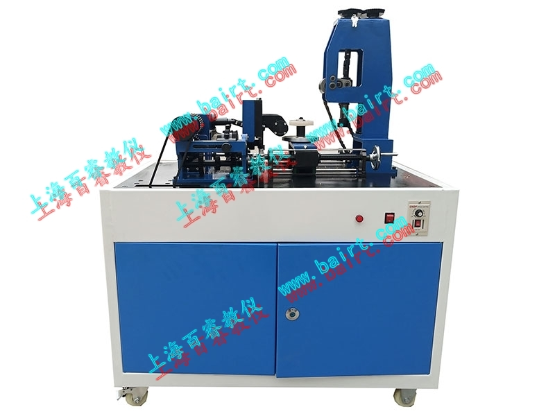
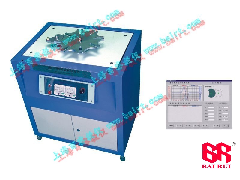
BR-CJJ-B Creative Gear Comprehensive Processing Transmission Analysis Training Platform
1) Experimental project:
Innovative analysis of the transmission principle of the gear hobbing integrated machine.
Analysis of the motion of the gear hobbing integrated mechanism (drawing a mechanism motion diagram to calculate the transmission ratio).
Gear cutting practical training: Students can use gear hobbing and hobbing methods to cut a total of 9 types of standard, positively modified, and negatively modified gears for three types of wax blanks.
Compare and analyze the machining characteristics of standard gears, positive displacement gears, and negative displacement gears. Compare and analyze the tooth profile characteristics of root cut gears and non root cut gears.
Assembly and disassembly experiments of mechanical transmission devices.
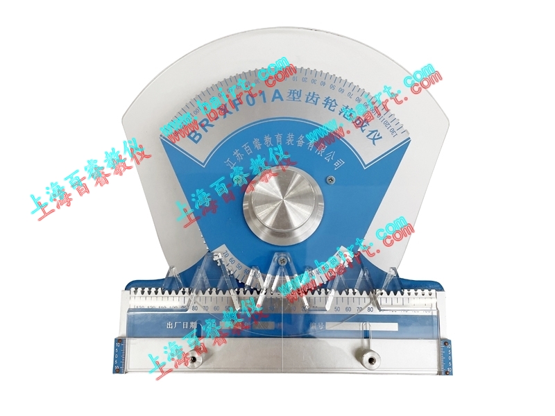
Experimental determination of mechanical parameters (gear parameters, dimensional tolerances, and positional tolerances).
2) Basic structure:

Creative gear comprehensive machining transmission analysis training platform
This machine is composed of a chassis, motor, variable speed mechanism, gear shifting mechanism, gear hobbing mechanism, gear blank tray mechanism, gear hobbing mechanism, etc.
1. The chassis is made of high-quality cold-rolled steel plate with a thickness of 2mm and is made of sheet metal. The dimensions are: length 840X width 460X height 665mm, and the lower part is equipped with four sets that comply with the national standard GB/T14688 ϕ 50 industrial casters; The upper part is equipped with a vulcanization table panel with a length of 1000X width of 566X thickness of 15mm. The front part is equipped with a standard control box, and the rear part is equipped with a cabinet door. The chassis can accommodate measuring tools.
2. Motor: Power P=90W, speed n=stepless speed change: 0-180 r/min
3. Transmission mechanism:
Rolling insertion switching gear mechanism
Gear hobbing mechanism
Toothed blank tray mechanism
Gear shaping mechanism
Main functions:
1. The mechanical transmission route diagram of this training platform is shown in the following figure:

Figure: Transmission Roadmap of BR-CJJ-B Creative Gear Comprehensive Processing Transmission Analysis Experimental Platform
This training platform is only equipped with a 90W reduction motor. After the power is output by the V-belt transmission I, it is divided into two routes: 1-3-4 and 1-2-14, and then further divided into five transmission routes: 9-10-12-12-13 and 5-6-9-8, 20-21-22-23-24-25, 15-16-17-18-19 and 15-26-28, which drive the left and right movement of the tray (respectively achieving feed motion of gear rolling and gear inserting). In addition, the speed ratio between the five transmission routes of manual spiral transmission is strictly related.
The schematic diagram of the mechanical transmission mechanism of this training platform is shown in the following figure
2. Rolling insertion switching gear mechanism 4
The deceleration motor of this training platform is equipped with a stepless speed controller, with output speed adjustable from 0 to 100%. The rotational motion and power of the motor are transmitted through V-belt transmission 1 to worm gear transmission 2 for primary diversion. One path is driven by cylindrical gear transmission 3 at the end of the worm shaft, and then to the gear shifting mechanism 4. The gear shifting mechanism is shown in the following figure.

Figure: Gear mechanism 4 for rolling and switching gears
When the fork of the rolling and cutting mechanism is moved to the leftmost position, the power diameter 4-5-6-7 is transmitted to the gear hobbing cutter 8, and its speed is equal to the motor speed; When the fork is moved to the far right end, power is transmitted to the tool insertion sleeve through 9-10-12-13, causing the tool to perform up and down cutting and tool movement. The crank of the crank rocker mechanism 12 rotates once, and the gear insertion tool completes a gear insertion work cycle of tool retraction return return return, with the crank speed being the same as the motor speed; When the fork is moved to the middle position, the shift gears do not mesh and cannot roll or insert teeth.
3. Transmission mechanism
The other way is that the power is reduced by worm gear transmission 2 (1:40), and then transmitted to the sliding triple gear through the spline part on the worm gear shaft. The triple gear transmission 14 can output in three gears: 36:24, 40:20, and 30:30. Through chain transmission 20, the hob holder is driven up and down by 20-21-22-23-24, thereby achieving cutting motion of hobbing teeth; Through chain transmission 15, the cutter is driven to rotate by 15-16-17-18-19, and the tooth blank tray is driven to rotate by 15-26. The cutting speed of this training platform is the same as the speed of the gear blank tray, so the number of teeth in the inserted gear is the same as the number of teeth in the inserted tool, corresponding to the three levels of speed change of the triple gear. By replacing the inserting tool and blank, three types of gears with z=20, 30, and 40 can be inserted. The variable speed mechanism is shown in Figure 6. When the speed shift fork is moved to the "20" position, a gear with z=20 can be rolled out; When the speed shift fork is turned to the "40" position, a gear with z=40 can be rolled out; When the gear shift fork is turned to the "30" position, the speed ratio is 2:3, and the speed of the hob and gear blank does not match, resulting in a phenomenon of disordered teeth.


During gear hobbing, there must be three relative movements between the tool and the blank: generative motion (rotation of the tool blank), cutting motion (up and down motion of the tool), and feed motion (movement of the workpiece).
The gear hobbing transmission chain completes two movements of the hob: the first is the rotational motion of the hob 8, which is driven by the driven bevel gear of the transmission route 2-3-4-5-6-7 to rotate the hob 8 axis; The second is the up and down motion of the rolling cutter (cutting motion), which is determined by the transmission route 2-14-20-21-22-23-14. The slider of the crank slider mechanism 14 is fixedly connected to the rolling cutter holder, achieving the up and down movement of the rolling cutter holder in the frame guide rail. The crank rotates once, and the rolling cutter holder moves up and down once, with a designed stroke of 30mm.
5. Gear transmission chain
The toothed transmission chain is shown in the following figure

During gear hobbing, there must be four relative movements between the tool and the blank, namely, generative motion (rotation of the tool and the blank), cutting motion, feed motion, and letting the tool move.
When inserting gears, the cutting tool not only rotates, but also has up and down cutting motion and tool movement. The rotation of the insertion tool is driven by 16 pairs of helical cranks and 17 straight bevel gear drives the spline sleeve, spline shaft, universal coupling, and insertion tool rod to rotate.
When inserting gears, the inserting tool and the letting tool not only rotate but also have up and down cutting movements. The self rotation of the insertion tool is transmitted by a pair of helical gears, which drive the spline sleeve, spline shaft, and universal coupling in the opposite direction through a pair of straight cylindrical gears, and the insertion tool shaft rotates.
The design of this machine adopts a crank rocker mechanism to achieve the up and down cutting motion of the insertion tool and the tool movement. The power is input by the sprocket, which drives the crank wheel to rotate. The trajectory of the connection point between the connecting rod and the tool insert sleeve conforms to the cutting motion - the motion trajectory of the tool.
6. Toothed blank tray drive chain
The gear blank tray drive chain is shown in the following figure

The hobbing and slotting of this training platform share a gear blank tray 28, and the gear blank to be processed is installed on the gear blank tray. The tooth blank tray must be able to rotate (as part of the movement) and move. Its rotation is driven by the triple gear variable speed transmission 14 through the chain transmission 15 and the spiral gear transmission 26, and its speed is the same as the speed of the cutter when inserting teeth; On the one hand, its movement is to move the gear blank to the hobbing or hobbing station during gear hobbing and hobbing conversion. On the other hand, it is to achieve feed motion during gear hobbing or hobbing processing, and can also achieve positive or negative gear shifting during gear machining. The movement of the tooth blank tray is manual. The handwheel rotates the spider screw transmission 27, dragging the tooth blank tray to move left and right on the slide rail. The amount of movement is controlled by the pointer and scale.
7. crank rocker mechanism 12
During gear shaping, the cutter moves back and forth, with its downward motion being cutting motion and its upward motion being return stroke. In order to avoid tool scratches on the newly machined tooth surface of the workpiece and reduce tool wear during the return journey, there should be a certain gap between the tool and the workpiece. After the end of the return journey and before the next cutting stroke begins, the insertion tool should return to its original position. The movement of the insertion tool to move away and return to its original position is called tool movement.

The driven sprocket shaft of chain drive 11 drives crank A B to rotate around point A, rocker C D to swing around point D, and connecting rod B C to perform planar motion. Through institutional synthesis, i.e. adjusting the length dimensions of A B, B C, C D, A D, and C E, the trajectory of a point E on the connecting rod B C (on the extension line of B C) is in a "D" shape, which meets the requirements for the insertion of the knife.
The motion diagram of the crank connecting rod mechanism 12 is shown in the following figure

Figure: Schematic diagram of the motion of the crank rocker mechanism 12. The following figure shows the position curve of the E-point trajectory on the connecting rod in the height time coordinate during the gear insertion process. From the graph, it can be seen that the cutting engineering travel time is longer than the return travel time, which achieves "fast return" and saves time. The vertical movement distance of the insertion tool is about H=6.8- (-26.2)=33mm

Technical parameters:





 Return to homepage
 Immediately call for consultation
 About Us
 Immediately consult online